Six Core Application Scenarios and PCB Design Considerations for Welded Circular Connectors

Six Core Application Scenarios and PCB Design Considerations for Welded Circular Connectors

Summary

Welded circular connectors are important electrical interfaces in industrial equipment, control systems, and electronic devices. When circular connectors are mounted on printed circuit boards (PCBs) using soldered terminals, their reliability depends on more than the connector itself. PCB footprint accuracy, solder joint quality, mechanical support, electrical performance, and environmental protection all influence the final assembly.

Six Core Application Scenarios and PCB Design Considerations for Welded Circular Connectors

Introduction

Welded circular connectors are important electrical interfaces in industrial equipment, control systems, and electronic devices. When circular connectors are mounted on printed circuit boards (PCBs) using soldered terminals, their reliability depends on more than the connector itself. PCB footprint accuracy, solder joint quality, mechanical support, electrical performance, and environmental protection all influence the final assembly.

This guide explores six core application scenarios for PCB-mounted circular connectors, explains essential PCB design considerations, and provides a practical selection framework for engineers and purchasing teams.
Circular Connectors
Circular Connectors
Rugged, compact and versatile — ideal when you need mixed power & signal plus environmental protection.

What Are Welded Circular Connectors?

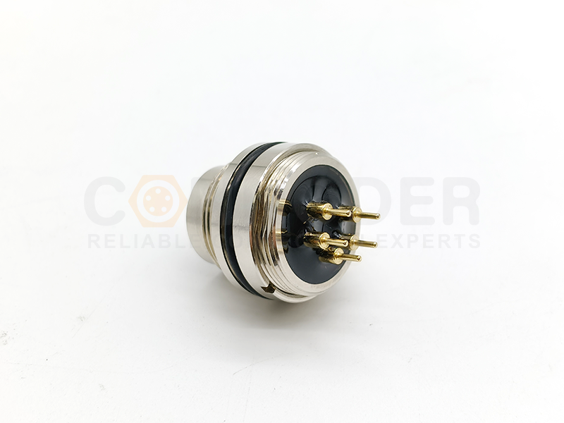
Circular connectors are electromechanical components designed to transfer power, signals, or data between electronic devices, cables, and equipment. Their circular form factor can provide a compact interface with features such as threaded coupling, keying, shielding, and environmental sealing, depending on the design.

PCB-mount circular connectors are designed to integrate with a printed circuit board through a specified terminal arrangement. Depending on the product, the connector may be mounted directly to the PCB, secured to an equipment panel, or supported by additional mechanical hardware.

Main Components of a PCB-Mount Circular Connector
Contacts: Conductive elements that carry electrical current or signals.
Insulator: Maintains contact spacing and electrical separation.
Housing: Protects the contact assembly and provides structural support.
Mounting features: Position and secure the connector within the equipment.
Sealing and shielding features: Optional elements that help address environmental protection and electromagnetic compatibility requirements.

Why Does PCB Integration Matter?
A connector may meet its electrical specifications but still perform poorly if the PCB footprint is inaccurate or the mounting structure is inadequate. Common integration problems include incorrect pin spacing or hole dimensions, insufficient clearance around the connector body, excessive mechanical stress on solder joints, inadequate current capacity, poor grounding, and incorrect sealing at the equipment interface.

Connector selection should therefore be considered together with PCB layout, mechanical design, and manufacturing requirements.

Six Core Application Scenarios for Welded Circular Connectors

PCB-mounted circular connectors can support a variety of industrial and electronic applications. The appropriate configuration depends on the electrical interface, installation space, mechanical loads, and environmental conditions.

1 Industrial Automation and Control Systems
Industrial automation systems use electrical connectors to link controllers, sensors, actuators, distributed I/O modules, and machine interfaces. PCB-mounted circular connectors can be integrated into compact control modules and equipment interfaces where reliable electrical connections are essential.

Typical requirements:

Stable power and signal transmission.
Appropriate contact count and coding.
Mechanical retention under expected mating forces.
Compatibility with the PCB and equipment enclosure.
Suitable environmental protection.
PCB design considerations: Verify the connector footprint, pin layout, mounting dimensions, and enclosure clearance before fabrication. Place the connector where installation and maintenance are practical. If the connector will experience repeated mating or external cable forces, evaluate panel mounting or additional mechanical support instead of relying exclusively on solder joints.

CONNODER offers industrial circular connector families, including M8, M12, and M16, that can be evaluated for suitable automation and control applications. Confirm the available mounting style and electrical specifications for the exact part number.

2 Robotics and Motion-Control Equipment
Robotic systems rely on motors, encoders, position sensors, controllers, and communication modules. These components need electrical interfaces that remain reliable under the mechanical conditions of the equipment. Circular connectors may be used in selected robot control boards, motion-control modules, and embedded electronics.

Typical requirements:

Reliable connections under expected vibration and movement.
Suitable signal transmission for control and feedback circuits.
Appropriate current capacity for power connections.
Compact mounting dimensions.
Effective cable routing and strain relief.
PCB design considerations: Consider cable entry direction, connector accessibility, and clearance for mating and unmating. Avoid designs that transfer substantial cable loads directly to soldered terminals. For moving equipment, evaluate cable bending, vibration, shock, and repeated movement under representative conditions. Use suitable mechanical retention when required by the connector design.

3 Sensors and Measurement Instruments
Sensors and measurement instruments convert physical conditions into electrical signals. Examples include temperature, pressure, position, flow, and proximity measurement systems. Circular connectors may provide the interface between a sensing element, internal electronics, and an external cable or controller.

Typical requirements:

Reliable transmission of low-level signals.
Appropriate insulation and contact resistance.
Compact size.
Compatibility with the operating environment.
Suitable electrical separation and grounding.
PCB design considerations: Keep sensitive analog signal paths away from noisy switching circuits and high-current traces where practical. Plan the grounding arrangement carefully, and evaluate shielding where required by the application. For precision measurement systems, consider leakage paths, contamination, signal noise, and grounding as part of the complete circuit design.

Do not assume that every circular connector is appropriate for low-level measurement signals. Confirm its electrical specifications and compatibility with the intended circuit.


4 Industrial Ethernet and Data Communication
Industrial communication equipment connects controllers, switches, gateways, and distributed devices. Depending on the interface, circular connectors can provide connections for industrial Ethernet and other data communication systems. PCB-mounted circular connectors can link external connections with internal communication electronics in compact equipment.

Typical requirements:

Compatibility with the intended protocol and data rate.
Correct contact arrangement and coding.
Adequate signal integrity.
Suitable grounding and shielding.
Mechanical and environmental compatibility.
PCB design considerations: For high-speed signals, consider differential impedance, routing symmetry, return paths, connector transitions, and grounding-via placement. Avoid unnecessary discontinuities in differential signal paths. Follow the connector manufacturer's layout recommendations and the requirements of the selected communication interface.

Shielded connectors may help reduce electromagnetic interference, but performance depends on the complete system, including the connector shell, cable shield, PCB grounding, and equipment chassis.


5 Medical and Laboratory Equipment
Medical and laboratory instruments use electrical connections for monitoring, measurement, data acquisition, and equipment control. Circular connectors may be suitable for selected instruments requiring compact and secure electrical interfaces.

Typical requirements:

Reliable signal and power transmission.
Materials compatible with intended cleaning procedures.
Appropriate insulation and electrical separation.
Mechanical durability under expected service conditions.
Compliance with applicable equipment-level standards.
PCB design considerations: Review creepage, clearance, insulation, and leakage-current requirements according to applicable standards and the equipment's risk assessment. For devices exposed to frequent cleaning, verify the chemical compatibility of the housing and seals. An IP rating alone does not establish suitability for every disinfectant, sterilization method, or medical application.

For regulated medical equipment, connector selection must be part of the complete system-level safety evaluation.


6 Transportation and Heavy Machinery Electronics
Transportation equipment and heavy machinery use control units, monitoring systems, actuators, and distributed electronic modules. Depending on the application, these systems may experience vibration, shock, dust, moisture, and temperature changes. Circular connectors may be used in suitable control and monitoring assemblies when their specifications meet the operating requirements.

Typical requirements:

Secure mechanical retention.
Suitable operating-temperature range.
Resistance to expected vibration and shock.
Appropriate current and voltage ratings.
Environmental protection where required.
Compliance with application-specific qualification standards.
PCB design considerations: Verify the connector mounting arrangement and mechanical load path. Use appropriate supports where cable forces or repeated mating could stress the PCB. Evaluate temperature cycling and its effects on the connector, PCB, and solder joints. For safety-critical transportation applications, confirm that the selected component and complete assembly meet applicable industry and customer requirements.

A general-purpose industrial connector should not automatically be considered qualified for every automotive, railway, or safety-critical application.
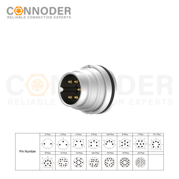
Essential PCB Design Considerations for Welded Circular Connectors

Reliable PCB integration requires the connector and circuit board to be designed as a complete electromechanical assembly. The following factors deserve particular attention.

PCB Footprint and Pin Layout
The PCB footprint defines the positions and dimensions of the pads or holes used to mount the connector. Incorrect dimensions can cause assembly difficulties, misalignment, poor solder joints, or interference with nearby components.

Footprint verification checklist
Contact pitch and pin positions.
Pin diameter and recommended finished-hole diameter.
Pad dimensions and annular-ring requirements.
Connector body dimensions and mounting-hole locations.
PCB edge clearance and adjacent component spacing.
Connector orientation and mating direction.
Use the exact manufacturer's mechanical drawing and recommended land pattern. Avoid creating a footprint based solely on a product photograph or approximate dimensions. If the connector is also secured to an enclosure panel, check the relationship between the PCB footprint, panel cutout, mounting hardware, and connector alignment.


 Through-Hole Soldering and Joint Reliability
Many PCB-mount circular connectors use through-hole solder terminals. The pins pass through the PCB and are soldered to the corresponding pads. Solder joint quality depends on connector design, PCB finish, hole and pad geometry, solderability, and the assembly process.

Follow the manufacturer's recommended hole and pad dimensions.
Confirm PCB plating and solderability requirements.
Use a soldering process compatible with the connector materials.
Respect thermal exposure limits for the connector and PCB.
Provide access for inspection and rework where practical.
Evaluate mechanical stress on soldered terminals.
When wave, selective, or manual soldering is used, ensure that the process is compatible with the connector materials and construction. For high-reliability applications, define inspection criteria and validate the assembly using prototypes and representative production testing.

A good solder joint does not eliminate the need for mechanical support when a connector experiences substantial external loads.

 Mechanical Fixation and Cable Strain Relief
Circular connectors may experience forces during mating and unmating. Cable weight, pulling, bending, and vibration can introduce additional stress. If these forces are transferred directly to the solder joints, they may contribute to cracked joints, lifted pads, or PCB damage.

Evaluate expected mating and unmating forces.
Determine how cable loads transfer to the PCB and enclosure.
Use suitable mounting hardware or retention features.
Provide appropriate cable strain relief.
Verify mechanical stability in the complete assembly.
For panel-mounted connectors, ensure that the panel and PCB mounting arrangement maintains alignment without forcing the soldered pins into position.


Grounding and EMI Shielding
Electromagnetic interference can affect communication reliability and sensitive electronic circuits. Connector-shell bonding and PCB grounding are therefore important considerations in many industrial applications.

For shielded circular connectors, determine how the conductive shell and cable shield connect to the equipment chassis and PCB grounding system.

Maintain an appropriate grounding path for the connector shell.
Follow the manufacturer's shielding recommendations.
Avoid unnecessary interruptions in high-frequency return paths.
Separate sensitive signal traces from major noise sources where practical.
Verify performance through suitable EMC testing.
The correct grounding method depends on the circuit architecture, cable shielding, operating frequency, and equipment-level EMC requirements. A shielded connector alone does not guarantee EMC compliance.

Current Capacity and Thermal Management
When a connector carries power, its electrical and thermal requirements must be evaluated together with the PCB layout. Relevant factors include rated current per contact, the number of simultaneously loaded contacts, contact resistance, copper trace width and thickness, PCB thermal properties, ambient temperature, and connector temperature-rise limits.

The permitted current may depend on the number of loaded contacts and the manufacturer's specified test conditions. Do not rely solely on a headline connector current rating. Evaluate the complete current path, including contacts, solder joints, PCB traces, and connected components.

For demanding power applications, perform thermal calculations and, where appropriate, temperature-rise testing on a representative assembly.

3.6 Environmental Protection and Enclosure Design
Industrial circular connectors may be selected for environments involving dust, moisture, oil, temperature changes, or other contaminants. Before choosing a connector, evaluate the required ingress protection, sealing at mating and panel interfaces, housing and seal material compatibility, operating temperature, condensation and corrosion risks, and cable-entry requirements.

An IP rating applies to a specified connector configuration and test conditions. It should not automatically be treated as the protection rating of the entire assembled device. A connector may not provide the expected protection if the mating interface is open or the panel gasket is incorrectly installed.

 High-Speed Signal Integrity
When circular connectors carry Ethernet or other high-speed signals, PCB design must account for the electrical behavior of the complete interconnect.

Differential impedance.
Trace geometry and routing symmetry.
Signal return paths.
Connector transition geometry.
Via placement and parasitic effects.
Crosstalk and electromagnetic coupling.
Cable and connector compatibility.
Use the manufacturer's technical documentation and relevant interface specifications to establish design requirements. Simulation or measurement may be appropriate for demanding applications.

Manufacturing and Assembly Compatibility
The connector footprint must also be compatible with the intended PCB fabrication and assembly process. Confirm that the mounting technology is supported, hole and pad dimensions comply with fabrication capabilities, the connector can be placed consistently, soldering equipment can access the required joints, inspection and rework are practical, and the process respects the connector's thermal limits.

A design review involving the PCB designer, connector supplier, and assembly manufacturer can identify manufacturing risks before production.

Conclusion

Welded circular connectors ore precisely described as PCB-mounted circular connectors with soldered terminals when applicable rovide an important interface between electronic assemblies and external equipment.

Their reliability depends on more than connector selection. Engineers must also consider footprint accuracy, solder joint quality, mechanical retention, current capacity, thermal management, shielding, environmental protection, and manufacturing compatibility.

By evaluating these factors across industrial automation, robotics, sensing, communication, laboratory equipment, and heavy machinery applications, design teams can make better-informed connector decisions and reduce avoidable integration problems.

CONNODER offers a range of industrial circular connector families for evaluation in suitable applications. Review the relevant product specifications and discuss your PCB interface requirements with the manufacturer to identify a configuration that fits your design.
What are welded circular connectors?

Welded circular connectors are circular electrical connectors that use soldered connections to establish electrical continuity between contacts and conductors or circuit boards. Depending on the product design, they may use solder terminals, PCB solder pins, or other solder-termination structures. They are commonly used in industrial equipment where reliable electrical connections and compact installation are required.
What are the main applications of circular connectors with solder terminals?

Circular connectors with solder terminals are widely used in industrial automation, robotics, sensors and measurement equipment, industrial communication systems, medical and laboratory instruments, and transportation machinery. The appropriate connector depends on the electrical requirements, environmental conditions, mounting method, and mechanical loads of each application.
What should be considered when designing a PCB for circular connectors?

Key considerations include the connector footprint, pin spacing, hole diameter, solder-joint reliability, mechanical retention, grounding, EMI shielding, current capacity, thermal management, and signal integrity. Designers should always follow the manufacturer's dimensional drawings and recommended PCB layout specifications to ensure compatibility and reliable assembly.
How can the reliability of soldered circular connectors be improved?

Reliability can be improved by selecting compatible PCB materials and connector terminals, optimizing soldering parameters, providing adequate mechanical support, preventing excessive cable loads, and ensuring proper grounding and environmental protection. Inspection and testing should also be performed to identify solder defects and verify electrical continuity.
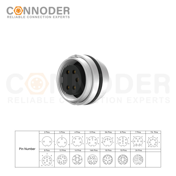
Wholesale M16 6 Pin Circular Connector | Rear Panel Mounted Welded Type Connector Ip67 Waterproof, Industrial Automation Signal Connector
M16 6 Pin Circular Connector A-Code Interface, Waterproof Connector Receptacle Cable, Straight, Front-Locking, Unshielded
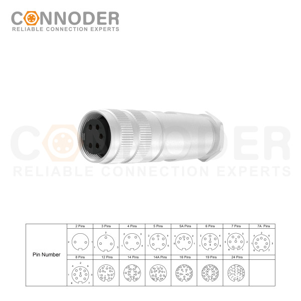
Wholesale M16 Female 6 Pin Circular Connector |  Waterproof Straight Solder Cable Front Fastened Industrial Automation Connector(M18*0.75)
M16 6 Pin Circular Connector assemblies are ideal for demanding industrial applications such as industrial automation and aerospace, marine, and telecom systems.
Wholesale M16 Female 6 Pin Straight Female Solder Circular Connector | Assembled Metal Housing C091 Plug Waterproof Connector
M16 6 Pin Circular Connector are ideal for demanding industrial applications such as industrial automation and aerospace, marine, and telecom systems. M16 Circular Connector are available in quick-lock wiring assembly types with IP67 protection and a vibration-resistant screw design.
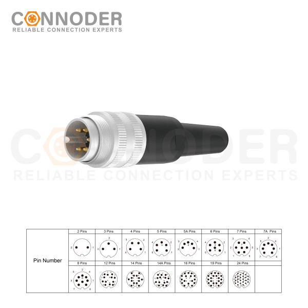
Wholesale M16 Male 5 Pin Circular Connector |  waterproof IP65 Straight Metal Plastic Solder Assembly plug 2 3 4 5 6 7 8 12 14 16 19 24Pin with Plastic Tube
M16 6 Pin Circular Connector are ideal for demanding industrial applications such as industrial automation and aerospace, marine, and telecom systems. M16 Sensor connector are available in quick-lock wiring assembly types with IP67 protection and a vibration-resistant screw design.